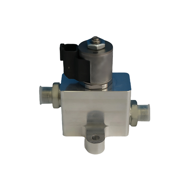
Precautions for Using Proportional Valves in Industrial Manufacturing As key components for precise control of flow and pressure via electrical signals
The following considerations are crucial for the proper use of proportional valves in industrial manufacturing to ensure stable system operation and extended service life:
I. Type Selection and Matching
Technical Parameter Alignment
Select valves based on application requirements such as system pressure, flow rate, and control accuracy. For example:
Choose proportional flow valves with excellent flow characteristics and high resolution for high-precision flow control scenarios.
Opt for valves rated for the system's pressure class (e.g., ≥31.5MPa for high-pressure systems).
Medium and Functional Compatibility
Ensure the valve is suitable for the working medium (e.g., hydraulic oil, gas, water). Some proportional pressure valves require specific pilot pressure ranges for stable operation.
II. Installation Requirements
Positioning and Environmental Factors
Install the valve in a location that facilitates installation, debugging, maintenance, and repair. Avoid environments with high temperatures, humidity, dust, or vibration, as these can degrade valve performance and lifespan.
Maintain safe distances from heat sources (e.g., ≥500mm from steam pipes) and use anti-vibration mounts for machinery with dynamic loads.
Pipeline Connection Standards
Ensure secure, leak-free connections with appropriate seals (e.g., O-rings for hydraulic systems). Match pipeline inner diameter to valve port sizes (e.g., DN20 valve with Φ22mm pipeline) to minimize pressure loss and flow pulsation.
Install according to the flow direction marked on the valve body; reverse installation may cause spool jamming or control failure.
Filter Installation
Install a 10–20μm precision filter upstream of the valve (e.g., a high-pressure pipeline filter for hydraulic systems). For critical applications, use a duplex filter to enable online replacement without system shutdown.
III. Electrical Connection and Protection
Wiring and Signal Transmission
Follow the valve manual for electrical connections, using shielded cables (e.g., RVVP 4×0.75mm²) to reduce electromagnetic interference (EMI). Ground the shield at the control cabinet to prevent signal distortion from motors or inverters.
Verify wiring with a multimeter to avoid loose connections, short circuits, or reverse polarity (e.g., misconnecting +24V and GND in solenoid coils).
Electrical Protection Measures
Use IP65-rated enclosures for valves in wet/dusty environments, and apply anti-corrosion coatings (e.g., zinc-nickel plating) in coastal or chemical plant settings.
In explosive atmospheres (Zone 1/2), select ATEX-certified valves with flameproof enclosures (Ex d) and install explosion-proof cable glands.
IV. Debugging and Calibration
Initial Commissioning
Before start-up, inspect mechanical connections (bolts, flanges), electrical wiring (insulation resistance ≥10MΩ), and spool position (manually operate the valve to check for sticking).
Perform no-load testing with low-pressure fluid (e.g., 2MPa) to observe valve response; abnormal noise or vibration may indicate misalignment or air in the system.
Precision Calibration
Use professional equipment (pressure transducers, turbine flow meters) to calibrate the valve’s input-output relationship (e.g., 4–20mA signal corresponding to 0–100% flow).
Record calibration data (e.g., voltage-flow curves) for future reference, and re-calibrate annually or after 5,000 operating cycles.
V. Working Medium and Environmental Control
Medium Specifications
Adhere to medium requirements:
Hydraulic Oil: Use ISO VG 46 oil with cleanliness ≥NAS 8, water content <0.05%, and acid value <0.1mgKOH/g.
Pneumatic Systems: Use compressed air with dew point <–20°C and particle size <5μm (ISO 8573-1 class 4.4.4).

Temperature Management
Operate within the rated temperature range (–20°C to +80°C for most valves). For extreme temperatures:
Install electric heaters (e.g., 200W/m²) in cold environments to maintain oil viscosity (≥15cSt).
Use water-cooled heat exchangers in high-temperature settings to prevent seal aging (NBR seals degrade above +100°C).
VI. Maintenance and Servicing
Routine Inspections
Monthly Check: Inspect joints for leakage (use UV dye for hard-to-see leaks), check solenoid coil temperature (≤70°C), and verify pressure stability with a gauge.
Quarterly Test: Use a diagnostic tool to measure valve response time (≤50ms for proportional flow valves) and compare with baseline data.
Fluid Management
Test oil properties (viscosity, water content, particle count) every 1,000 hours. Replace oil based on usage:
Normal conditions: Every 2,000–3,000 hours (or annually).
Harsh conditions: Every 1,000 hours (e.g., in foundries or construction machinery).
Valve Cleaning and Overhaul
Disassemble and clean the spool every 6 months (or after 10,000 cycles) using non-corrosive solvents (e.g., isopropyl alcohol). Avoid metal tools that may scratch the spool surface.
Proactively replace wear parts: O-rings (annually), coil seals (every 2 years), and spool assemblies (after significant wear).
